
PROJECT
Modular Printer Enclosure · 3D Layout V1
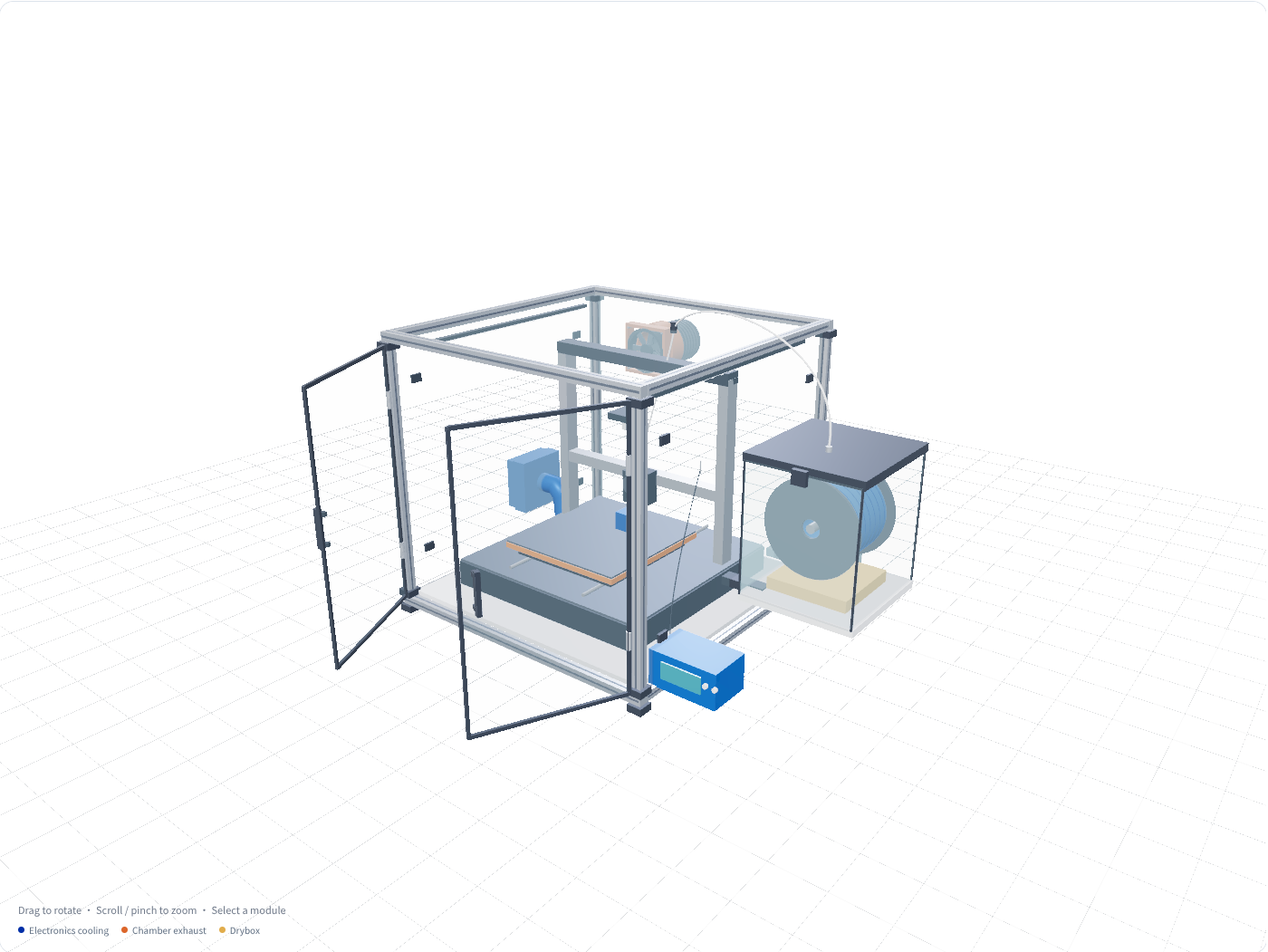
Explore a 2020 frame, double doors, electronics cooling, a separate filament drybox and chamber exhaust. Rotate, zoom, open the doors and download the original GLB concept model.
Preparing the 3D layout view. You can also download the GLB.
Preparing the 3D layout view. You can also download the GLB.
From layout to a physical build
Measure the printer and its full motion envelope
Check the printer body, full bed travel, cable bends, filament routing and service access before adjusting the proposed 650 × 650 × 600 mm outer frame. The generic printer shown is an occupancy placeholder.
Confirm the frame, doors and removable panels
Use 2020 extrusions, transparent double doors and removable side and roof panels. Recalculate panel dimensions for the final connectors, seals and hinges. Manufacturing hole locations are not included in this model.
Adapt cooling, exhaust and filament storage separately
The cooling bay takes external air through a sealed duct to the original electronics intake. Chamber exhaust sits at the rear upper side. The drybox is outside on the right, using desiccant storage and PTFE filament routing.
Fit external temperature control and validate
V1 uses an off-the-shelf thermostat and probe. Check temperature, airflow, feed resistance, door operation and service access before finalizing the fans, filter cassette and purchasing list.
Design references & model provenance
This concept uses original schematic geometry authored for XMake Lab and arranged around the proposed enclosure layout. The projects below are module design references; their CAD and printable parts are not copied into this model. Check each project’s interfaces and license separately.
- cage3d: parametric enclosure frames and panels.
- Clicky Clack Fridge Door: removable doors and sealing details.
- Duct and Fan Fittings: fan and duct adapters.
- Nevermore Micro V6: serviceable recirculating filter cassettes.
- Filament Dry Box: separate filament storage and feed interfaces.
The viewer uses Threepipe (Apache-2.0). This preview does not establish printer compatibility or structural and thermal performance.